White LED
At a glance
Role in this project: the low-water warning indicator, lights up when the tank runs empty. In your kit: ×3 You've seen this before: in Your First Program you wired and blinked this exact module. This page recaps the wiring and shows how it'll be used in Smart Agriculture.
Why an LED in an irrigation system?
In real smart-irrigation systems, the controller needs to tell the gardener when something needs human attention, and the most universal "look at me" signal is a light. In this project, the White LED is on when the water tank is empty (the plant can't be watered until you refill it) and off the rest of the time.
So instead of blinking on a fixed schedule like in your first program, the LED here will be controlled by logic: if water level is low → LED on, else → LED off.
How it works
When the ESP32 sends a HIGH signal to the LED's S (Signal) pin, current flows through the LED and it lights up. When it sends LOW, the LED turns off.
The resistor is built in
Without a resistor, an LED would draw too much current and burn out. Your module has a 220 Ω resistor pre-soldered on the breakout board, so there's nothing to do: plug and play.
Specifications
| Property | Value |
|---|---|
| Operating Voltage | 3.3 V – 5 V |
| Pin Type | Digital Output |
| Built-in Resistor | Yes (on the module) |
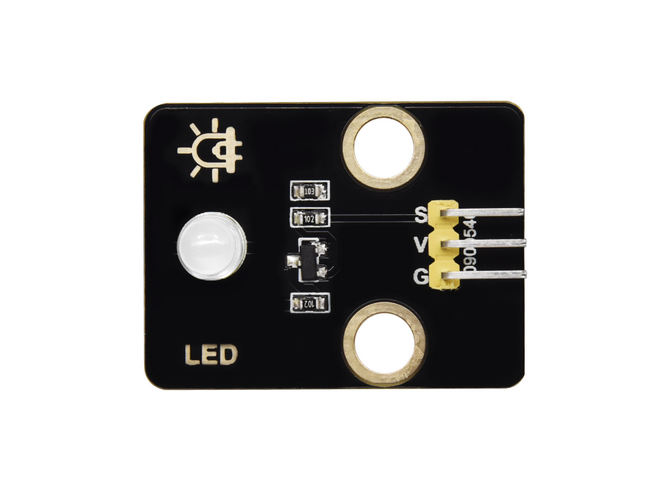
Pin layout
| LED Module pin | ESP32 Plus pin | Wire |
|---|---|---|
| S (Signal) | IO 27 | 🟡 Yellow |
| V (Voltage) | V on the same header | 🔴 Red |
| G (Ground) | G on the same header | ⚫ Black |
A single 3-pin Dupont cable carries all three connections at once.
Wiring
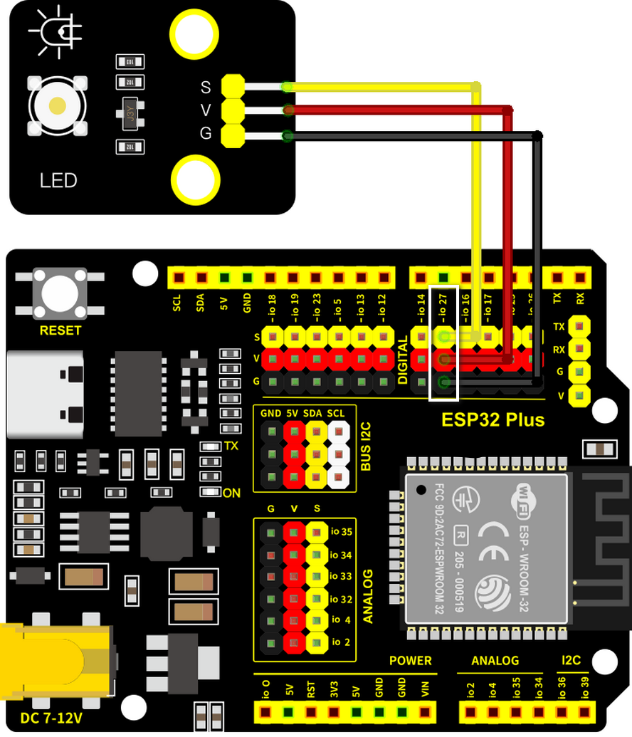
If you're rebuilding from scratch:
- Unplug the USB cable from your ESP32 Plus.
- Plug a 3-pin Dupont cable into the LED module (match S/V/G).
- Plug the other end into the IO 27 header on the ESP32 Plus.
- Plug the USB cable back in.
Already wired from First Program?
Leave it as-is. You'll add three more modules (soil probe, water-level detector, relay) on different pins; they don't conflict.
How you'll use it in this project
In the full build, the LED block goes inside an if / else from the Control category:
| Situation | LED block | What the gardener sees |
|---|---|---|
| Tank is empty (water level < 500) | set LED on pin GPIO 27 to ON |
LED lit: refill the tank |
| Tank has water | set LED on pin GPIO 27 to OFF |
LED dark: all good |
The exact decision logic comes together in Build the Smart Agriculture System once you've also met the soil moisture probe, water-level detector, and pump.