Pin Map & Shield Layout
This is the single source of truth for which ESP32 Plus pin every component in your kit uses throughout this tutorial. Bookmark this page; you'll come back to it often.
How wiring works on your kit
Every sensor in your kit ships on a small breakout board with three pins:
- G: Ground (black)
- V: Voltage (red), either 3.3 V or 5 V depending on the sensor
- S: Signal (yellow, sometimes other colours), the actual data line
Each sensor comes with a 3-pin Dupont cable that plugs into both the sensor module and the matching G/V/S header on the ESP32 Plus shield. You never need a breadboard, and you never strip or solder wires.
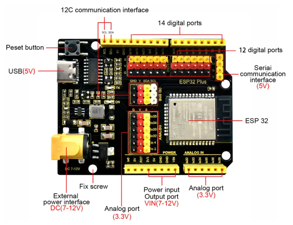
ESP32 Plus shield at a glance
Use this labelled diagram as your map. The pin tables further down refer to the IO numbers shown here.
Default pin assignments
The screenshots, starter programs, and troubleshooting tips in every tutorial assume these pins. Stick with them for your first pass through each lesson.
🌿 Smart Agriculture (Part 2)
| Module | ESP32 Pin | Notes |
|---|---|---|
| White LED (low-water warning) | IO 18 | Digital out |
| Soil Moisture Probe | IO 32 | Analog in (input-only pin) |
| Water Level Detector | IO 33 | Analog in (input-only pin) |
| Relay Module (controls pump) | IO 19 | Digital out (HIGH = pump ON) |
| Water Pump | Wired through Relay | Pump itself plugs into the Relay's switched output |
🚦 Smart Parking (Part 3)
| Module | ESP32 Pin(s) | Notes |
|---|---|---|
| Distance Sensor (TRIG) | IO 12 | Digital out |
| Distance Sensor (ECHO) | IO 13 | Digital in |
| Servo Motor (gate) | IO 14 | PWM out |
| RFID Reader | SDA = IO 21, SCL = IO 22 | I²C bus |
| White LED (spot indicator) | IO 5 | Digital out |
🚨 Smart Safety (Part 4)
| Module | ESP32 Pin | Notes |
|---|---|---|
| Fire Detector | IO 32 | Digital in (LOW = flame detected) |
| Gas Leak Sensor | IO 39 | Analog in (input-only pin) |
| Active Buzzer | IO 26 | Digital out (HIGH = beeping) |
🌡️ Smart Temperature (Part 5)
| Module | ESP32 Pin | Notes |
|---|---|---|
| DHT11 Temperature & Humidity | IO 15 | Single-wire digital |
| DC Motor (Fan) | IO 25 | PWM out |
| LCD Display | SDA = IO 21, SCL = IO 22 | I²C bus, default address 0x27 |
The I²C bus: shared pins
The LCD Display and RFID Reader both speak I²C, which uses just two shared wires (SDA and SCL). This means both devices can be on the same SDA/SCL pair at the same time; the ESP32 addresses each one by its unique device address. You do not need a separate pair of pins for each I²C device.
On your ESP32 Plus shield, the I²C bus is broken out twice for convenience:
- Dedicated I²C interface header (labelled
GND V SDA SCL) near the top of the board - Same signals also reachable on IO 21 (SDA) and IO 22 (SCL) of the main pin rows
Power rails
Your ESP32 Plus has a dedicated power-rail header (labelled POWER) with:
- 3V3: 3.3 V regulated, for low-voltage digital sensors (DHT11)
- 5V: 5 V direct from USB / DC, for motors, servos, relay coils, ultrasonic sensors, buzzers
- GND: shared ground (every sensor's G pin connects back here via its cable)
- VIN: 7–12 V input from the DC barrel jack (used when running on battery)
Every G/V/S header already has G and V on it, so you don't usually need to touch the POWER rail directly. It's there for projects where you add an extra LED strip or a motor that needs its own supply.
Input-only pins to know about
On the classic ESP32, pins 34, 35, 36, 39 can only be read, never written. They're broken out as the Analog IN header on your ESP32 Plus shield. Use them for:
- Sensors you only read from (analog signals like Soil Moisture, Water Level, Gas Leak).
- Never try to "turn on" or "set HIGH" a device on these pins. Flowlence Code will let you, but nothing will happen.
Pins the tutorials avoid
Some ESP32 pins have special roles. Avoid them unless a tutorial explicitly tells you to use them:
| Pin(s) | Why to avoid |
|---|---|
| IO 0 | Boot-mode select, affects uploading |
| IO 1, IO 3 | Serial TX / RX, used by USB |
| IO 6 – IO 11 | Connected to internal flash: do not touch |
Safety conventions
Always disconnect USB before changing wiring
Moving a wire while the ESP32 is powered can short pins and damage the board. Unplug first, rewire, plug back in.
3.3 V vs 5 V sensors
Your ESP32 Plus powers each sensor with the right voltage automatically via the shield, as long as you plug the cable into the matching G/V/S header. The tutorials call out when a sensor is specifically 5 V only (most motors and ultrasonic sensors).